


Ask Fleece: How to Set Valve Lash on a 5.9/6.7L Common Rail Cummins
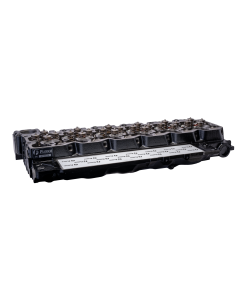
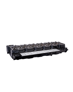
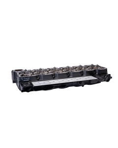
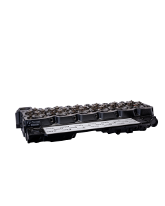
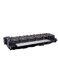
During the installation of your Fleece Performance Freedom Series 5.9L or 6.7L Cummins Cylinder Head, it is critical that you re-lash the valves.
INSTRUCTIONS FOR VALVE LASH
NOTE: To obtain accurate readings, valve lash measurement and adjustments should only be performed when the engine coolant temperature is less than 60 degrees C (140 degrees F).
STEP 1: Disconnect negative battery cables.
STEP 2: Remove valve cover.
STEP 3: Using the crank shaft bearing tool [Fleece P/N FPE-CCBT), rotate crankshaft to align damper TDC mark to 12:00 o’clock position.
a. If both rocker arms for number 1 cylinder are loose, continue to next step.
b. If both rocker arms are not loose, rotate crankshaft 360 degrees.
STEP 4: With the engine in this position, valve lash can be measured at the following rocker arms: Intake 1-2-4 / Exhaust 1-3-5. Measure the valve lash by inserting a feeler gauge between the rocker and rocker bridge. Refer to VALVE LASH LIMIT CHART for the correct specifications. If the lash measurement falls within the limits, adjustment/resetting is not necessary. If the lash measurement is outside the limits, adjustment is required.
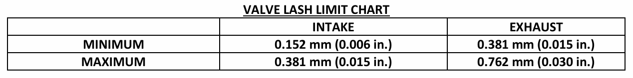
NOTE: If measured valve lash falls within these specifications, no adjustment is necessary. Engine operation within these ranges has no adverse effect on performance, emissions, fuel economy or level of engine noise.
STEP 5: If adjustment is required, loosen the lock nut on the rocker arms and turn the adjusting screw until the desired lash is obtained:
-Intake 0.254 mm (0.010 in.)
-Exhaust 0.508 mm (0.020 in.) Tighten the lock nut to 24 N.m (212 in-lbs) and recheck the valve lash.
STEP 6: Using the crankshaft barring tool, rotate the crankshaft one revolution to align the damper TDC mark to the 12:00 o’clock position.
STEP 7: With the engine in this position, valve lash can be measured at the remaining rocker arms: Intake 3-5-6 / Exhaust 2-4-6. Use the same method as above for determining whether adjustment is necessary and adjust those that are found to be outside of the limits.
STEP 8: Install valve cover.
STEP 9: Connect the negative battery cables.
Related Products

IMPORTANT: We will not be shipping product between the dates of July 5th and July 11th. All orders will be processed and shipped the week of July 12th.
While we are closed take advantage of 5% off MSRP!